I bought from a popular chinese store a generic Tuya smart plug with power monitoring. It was extrememly cheap, costing less than 4 EUR. And of course I bought it to play trying to flash ESPHome.
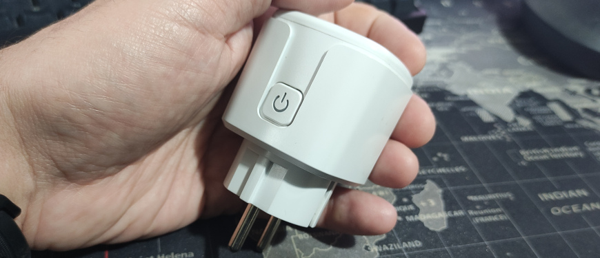
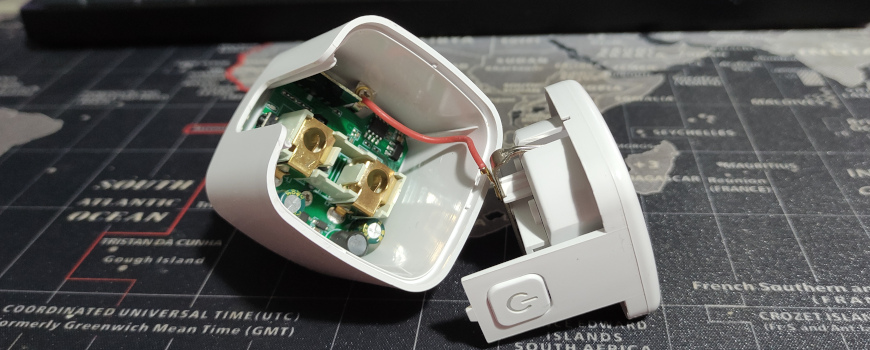
The first challenge was to open it without breaking it. I was able to open it by wrapping it in cardboard and gently tapping it with a hammer around the body.
You never know what chip you are going to find. In the past ESP8266 was very common but now they switched mainly to Beken chips. This smart switch has a T102_V1.1 board with a Realtek RTL8710BX chip:
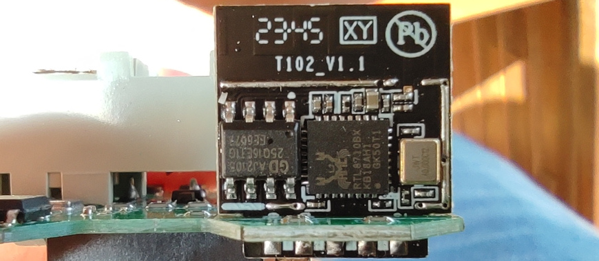
Luckily the support for this chip was developed in the LibreTiny project:
https://github.com/libretiny-eu/libretiny
And now it’s integrated into ESPHome:
https://esphome.io/components/libretiny
This is the board:
https://fcc.report/FCC-ID/2AU7O-T102V11/4540736.pdf
And after investigating the outputs, I reached this conclusion about them:
| Index | RTL8710BX | Connection |
| 1 | VDD | Connected |
| 3 | GND | Connected |
| 5 | GPIO_A18/UART0_RXD | Connected to the button |
| 7 | GPIO_A23/UART0_TXD | Not connected |
| 9 | GPIO_A14/PWM0 | Power Monitor SEL pin |
| 11 | GPIO_A15/PWM1 | Connected to the relay |
| 2 | GPIO_A12/PWM3 | Power monitor CF1 pin |
| 4 | GPIO_A0/PWM2 | Power monitor CF pin |
| 6 | GPIO_A5/PWM4 | Status LED inverted (there is another LED connected to the relay) |
| 8 | GPIO_A30/DEBUG_LOG_TX | Not connected, I soldered a cable to the flasher RX |
| 10 | GPIO_A29/DEBUG_LOG_RX | Not connected, I soldered a cable to the flasher TX |
ESPHome
I created one device this config in the ESPHome dashboard (without power monitoring, read below if you want to enable it):
substitutions:
  devicename: smartplug1
  friendly_name: Smart Plug 1

esphome:
  name: ${devicename}
  friendly_name: ${friendly_name}

rtl87xx:
  board: wr2
  framework:
    version: 1.5.1

logger:

api:
  password: ""

ota:
  password: ""

wifi:
  ssid: !secret wifi_ssid
  password: !secret wifi_password

  ap:
    ssid: ${friendly_name} Fallback Hotspot
    password: !secret wifi_password

captive_portal:

web_server:
  port: 80

status_led:
  pin:
    number: PA5
    inverted: true

text_sensor:
  - platform: libretiny
    version:
      name: LibreTiny Version

sensor:
  - platform: uptime
    name: Uptime
    filters:
      - lambda: return x / 60.0;
    unit_of_measurement: minutes

  - platform: wifi_signal
    name: Wifi Signal
    update_interval: 60s

binary_sensor:
  - platform: gpio
    device_class: power
    name: Button
    pin:
      number: PA18
      mode: INPUT_PULLUP
      inverted: true
    on_press:
      - switch.toggle: relay

switch:
  - platform: gpio
    id: relay
    name: ${friendly_name}
    pin: PA15
    restore_mode: RESTORE_DEFAULT_OFF
There is currently an open bug in LibreTiny and with the board t102-v1.1 the PA15 output does not work, so I needed to use the board wr2 on line 10.
I built it from the ESPHome dashboard and downloaded a .uf2 file.
Connecting an USB UART to the chip
I soldered four dupont cables to VDD, GND, GPIO_A29 and GPIO_A30 connecting them to an FTDI232 USB UART:
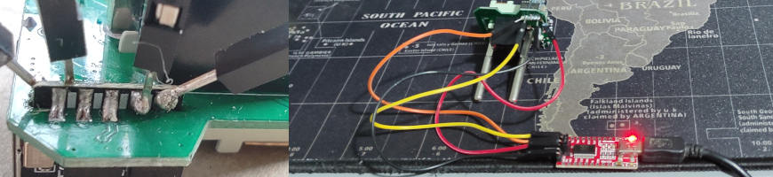
While connected to the FTDI232, the log from the chip can be viewed, i.e. with minicom (but remember to disable hardware flow control):
minicom -D /dev/ttyUSB0 -b 115200Flashing
The official flashing guide does not recomment to power the chip with the USB flasher, but it worked for me:
https://docs.libretiny.eu/docs/platform/realtek-ambz/#flashing
You need the ltchiptool tool, I installed it in a Python virtualenv:
python3 -m venv .
source bin/activate
pip install ltchiptool zeroconf
The ltchiptool GUI caused some segmentation fault, so I used it from the commmand line.
To put the chip in flash mode, we need to power it with the TX pin connected to GND.
In flash mode, I created a backup of the previous firmware:
ltchiptool flash read realtek-ambz flash-backup.binAnd to write the ESPHome firmware:
ltchiptool flash write smartplug1.uf2
After the flashing, if I try to power it from USB the WiFi module did not start and it causes a boot loop, but It worked perfectly plugging it into the mains power. A new device appeared in the router and I can connect to the ESPHome web dashboard.
Adding power metering
The plug includes a power metering chip: the BL0936, that is supported by ESPHome:
https://esphome.io/components/sensor/hlw8012.html
However, after configuring and uploading the firmware with the power meter enabled to the board, the device enters a boot loop, displaying the following error:
[D][switch:016]: 'Smart Plug 1' Turning OFF.
[D][binary_sensor:034]: 'Button': Sending initial state OFF
[C][hlw8012:014]: Setting up HLW8012...
W [      0.109] CHANGE interrupts not supported
Luckily, after 10 reboots, the firmware enters in the “OTA safe mode”, disabling all the modules and connecting to the WiFi without the web dashboard but opening a port to allow remote flashing.
https://esphome.io/components/ota.html
It is a problem in the combination of the RTL8710 chip and the BL0936 module, there is an open issue about this:
https://github.com/libretiny-eu/libretiny/issues/155
It can be fixed with the workaround of SuperXL2023 modifying the .esphome/platformio/platforms/libretiny/cores/realtek-amb/arduino/src/wiring_irq.c file and adding the lines 64 and 65:
62: #if LT_RTL8720C
63:                        event = IRQ_FALL_RISE;
64: #elif LT_RTL8710B
65:                        event = IRQ_RISE;
66: #else
67:                        LT_W("CHANGE interrupts not supported !!!!!!");
In the ESPHome config I’m specifying the version of the framework to avoid losing this fix in an automatic update. It works perfectly after rebuilding the image with this fix and uploading it to the device.
This is the complete ESPHome configuration with power metering:
substitutions:
  devicename: smartplug1
  friendly_name: Smart Plug 1

  voltage_divider: "1400"
  current_resistor: "0.001"
  current_multiply: "1.0"

esphome:
  name: ${devicename}
  friendly_name: ${friendly_name}

rtl87xx:
  board: wr2
  framework:
    version: 1.5.1

logger:

api:
  password: ""

ota:
  password: ""

wifi:
  ssid: !secret wifi_ssid
  password: !secret wifi_password

  ap:
    ssid: ${friendly_name} Fallback Hotspot
    password: !secret wifi_password

captive_portal:

web_server:
  port: 80

status_led:
  pin:
    number: PA5
    inverted: true

text_sensor:
  - platform: libretiny
    version:
      name: LibreTiny Version

sensor:
  - platform: uptime
    name: Uptime
    filters:
      - lambda: return x / 60.0;
    unit_of_measurement: minutes

  - platform: wifi_signal
    name: Wifi Signal
    update_interval: 60s

  - platform: hlw8012
    model: BL0937
    sel_pin:
      number: PA14
      inverted: true
    cf_pin:
      number: PA0
    cf1_pin:
      number: PA12

    current:
      name: Current
      filters:
        - multiply: ${current_multiply}
    voltage:
      name: Voltage
    power:
      name: Power
    energy:
      name: Energy

    update_interval: 30s
    current_resistor: ${current_resistor}
    voltage_divider: ${voltage_divider}

binary_sensor:
  - platform: gpio
    device_class: power
    name: Button
    pin:
      number: PA18
      mode: INPUT_PULLUP
      inverted: true
    on_press:
      - switch.toggle: relay

switch:
  - platform: gpio
    id: relay
    name: ${friendly_name}
    pin: PA15
    restore_mode: RESTORE_DEFAULT_OFF
It needs to calibrate the sensor to obtain the proper values of voltage_divider, current_resistor and current_multiply. It can be done with a multimeter and entering the values in the hlw8012 page.